HIGH TENSION CABLE
Why Crosslinked Polyethylene
Crosslinked Polyethylene insulated cables are durable, economical and the properties of the insulation offer considerable advantage over paper polyethylene and PVC, especially where current ratings and short circuit ratings are the primary objects.
What is Crosslinked Polyethylene
Polyethylene and PVC as cable insulate have a number of advantages over impregnated paper and this had led to their widespread adoption for power cable insulation. Polyethylene has high electric strength combined with low loss characteristics, which together with mechanical strength and nonhygroscopic nature gives it a superior insulation performance for both above ground and underground installation. Like PVC, polyethylene is a thermoplastic material with a relatively low melting point and will soften at sufficiently high temperature thus setting limitations on full load and short circuit ratings. PVC has a tendency to become brittle at temperatures below 0°C. Crosslinked Polyethylene is a thermosetting material achieved by processing to the vulcanization of polyethylene, yet retaining all the desirable properties of the original material; i.e polyethylene.
It allows greater current carrying capacity and higher overload and short circuits performance and where voltage drop is not a problem, a smaller size cable by comparison with PVC may be used with a resulting cost saving. The material has no true melting point and extensive tests with the Siolinx cable range have shown that the CrossLinked Polyethylene insulation remains elastic at high temperature consequently guaranteeing long and trouble free life. The cables described in this publication have a PVC sheath and are not suitable for installation in temperature below 0°C. CrossLinked Polyethylene insulated cables however, can be finished with other sheathing materials, e.g. polyethylene, to produce cables which can be handled and installed at temperature as low as 40°C.
The designs which Pioneer Cables Ltd. employ for the Siolinx range of Power Cables are based on BS-5467 and the latest IEC recommendations. The agreed insulation thickness for Crosslinked Polyethylene cable which have been adopted are those established by the IEC.
Jointing & Terminating
The techniques employed in the installation of low voltage Siolinx cables do not differ materially from those used for PVC insulated cables. For terminations, compression lugs and armour glands are interchangeable with those for PVC insulated cables to BS-6346, simplified joints employing mechanical conductor fittings in a cold pouring compound filled plastic protection box are widely available and are well suited to Siolinx cable constructions. Where soldering or hot pouring compounds are employed, the heat resisting properties of the insulation eliminate problems of distortion associated with PVC insulated cables.
The ruggedness and lightness of 11 kV Siolinx cable allows easy installation utilizing many of the techniques common to low voltage Siolinx and PVC cables.
Air insulated terminal boxes offering rapid cable disconnecting facilities can be used to advantage, and because of the simplified systems of stress control available these are little more difficult to install than low tension terminations. In addition to traditional joint designs which use hand applied self amalgamating tapes as the primary insulation, a system employing preformed rubber mouldings is available when maximum speed and simplicity of installation are of prime importance.
Different options for stress relieving such as:-
1) Taped stress control method
2) Slipon rubber moulded stress control method
3) Heat shrink tube stress control method
Details of various manufacturers dealing with jointing and terminating accessories could be given on request.
CONDUCTORS
Conductors are plain or annealed copper or aluminium complying with BS-6360.
INSULATION
Insulation consists of CrossLinked polyethylene which is applied by extrusion to form a compact homogeneous layer.
BEDDING
Bedding consists of extruded layer of black PVC compound copying to BS-7655.
ARMOUR
For Multicore Cables consists of a single layer of galvanized steel wires complying with BS-1442.
SERVING
The outer sheath is an extruded layer of black PVC complying with the requirements of Type 9 to BS-7655.
CORE IDENTIFICATION
Core identification is provided by colours.
SUSTAINED CURRENT RATINGS (50 Hz A.C.)
The current ratings given in the tables are suitable for close protection as defined in the IEE Wiring Regulations. Values are given for the three customary methods of installation; laid direct in ground, in ducts or in air. Generally the current rating will be reduced if there is a variation from the Standard conditions. The rating for most conditions can be calculated by multiplying the sustained current rating by the Factor(s) given in the appropriate adjustment table(s) Catelogue .
STANDARD CONDITIONS
The following conditions have been used to calculate the current ratings in the tables. Thermal resistivity of soil (g)* = 1.2° C m/W Standard Ground
Temperature = 15° C Ambient Air
Temperature = 25° C Maximum Conductor
Temperature = 90° C
Depth of burial, from ground surface to centre of cable, centre of duct or to centre of trefoil group of cables or ducts:
600/1000 V Cables = 0.5 m
1.9/3.3 kV Cables = 0.8 m
BENDING RADIUS
During installation, Siolinx cables should not be bent to a radius smaller than that given in the appropriate table in Catalogue.
DIMENSIONS AND WEIGHTS
Given in the tables are approximate in Catalogue.
OTHER CONSTRUCTIONS
It is possible to supply cable with minor difference in construction, if sufficient quantity is required.
In this connection, it should be noted that armoured cable to this specification aligns with the British Standard 5467; for 600/1000 volt and 1900/3300 Volt CrossLinked polyethylene insulated cable. Cable in accordance with IEC-60502 can be specially manufactured, the main differences being:
- Armour wire diameter may be one size smaller than IEC-60502 in isolated instances
- The PVC sheath thickness over armour is thinner than that required by IEC-60502 on all cables
OVERLOAD CONDITIONS
Crosslinked polyethylene cables can, without undue detriment, safey operate at an increased conductor temperature of 130°C subject to a maximum aggregate period of 36 hours per annum. The permissible current rating under overload conditions is given by multiplying the sustained current rating by the factor given in the appropriate adjustment table in Catalogue.
SHORT CIRCUIT CURRENT RATINGS
In addition to the normal sustained current ratings, consideration must also be given to short circuit ratings when selecting cable sizes.
VOLTAGE DROP (Vd)
This is mainly applicable to low voltage cables and can be calculated approximately using the following formula:
Vd = mv x I x L / 1000
where:
I = Current carried per conductor in amperes
L = Route Length in meters
Mv = approximate voltage drop/ampere/meter
Note:
The maximum allowable voltage drop is normally 2.5%
Under the IEE assessment of New Techniques Scheme the ANTS Committee has accepted 600/1000V XLPE Cables, as suitable for use in and around buildings subject to a maximum conductor temperature 85°C in line with IEC recommendations.
The current ratings in the catalogues are based on a maximum conductor temperature of 90°C and the derating factors applicable to 85°C. If cables are buried in the ground and loaded continuously, consideration should be given to the possibility of local increase in soil thermal resistivity due to moisture migration, making it desirable to reduce the maximum conductor operating temperature to 80°C. A conductor operating temperature of 90°C is only recommended if the thermal resistivity of the soil in dry conduction is known and is used in calculation of the current rating.
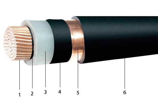
Single Core Cable
1. Conductor Compacted Circular Stranded Copper or Aluminium Conductor
2. Conductor Screen Extruded Semi Conducting Layer
3. InsulationXLPE
4. Insulation ScreenExtruded Semi Conducting layer with Copper Tape or Semi Conducting Tape with Copper Tape
5. Metallic Screen Plain Copper Tape
6. OversheathPVC
Note : Can also make Aluminium Wire Armoured
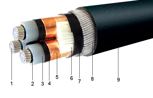
Three Core Cable Single Wire Armoured Cable
1. Conductor Compacted Circular Stranded Copper or Aluminium Conductor
2. Conductor Screen Extruded Semi Conducting Layer
3. InsulationXLPE
4. Insulation ScreenExtruded Semi Conducting layer with Copper Tape or Semi Conducting Tape with Copper Tape
5. Metallic Screen Plain Copper Tape
6. OversheathPVC
Note : Can also make Aluminium Wire Armoured


